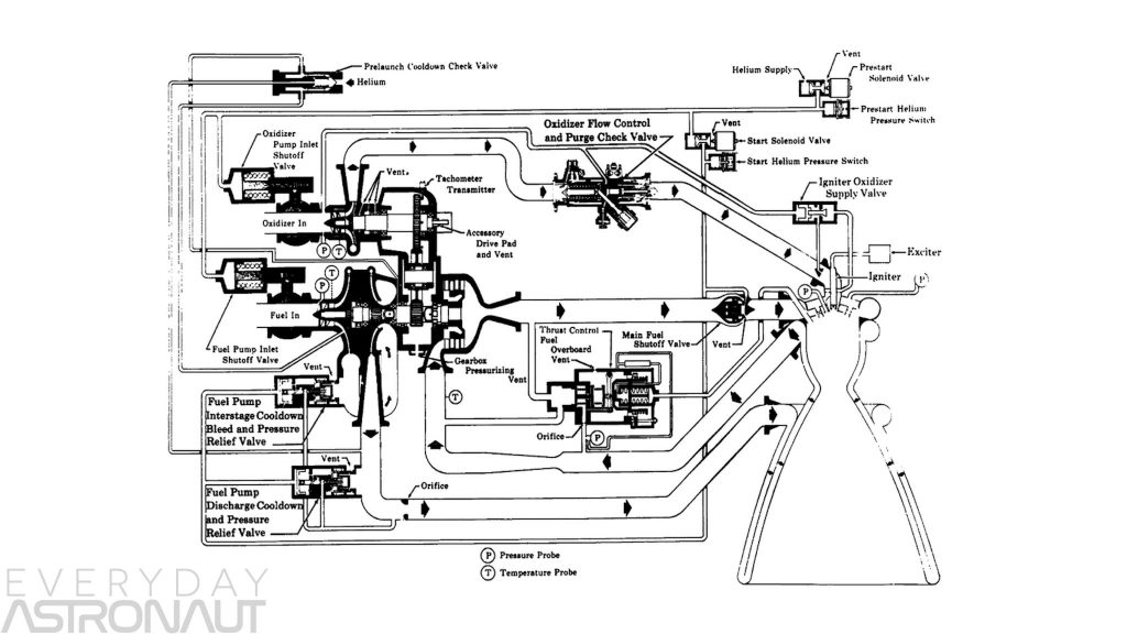
Schematic F1 Rocket Engine Diagram
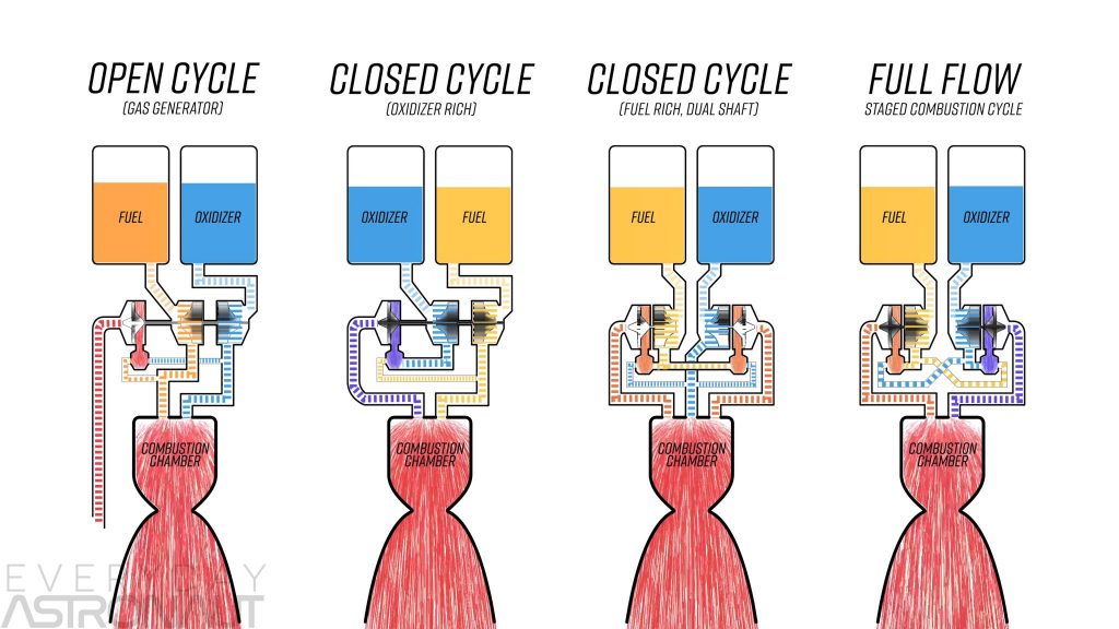
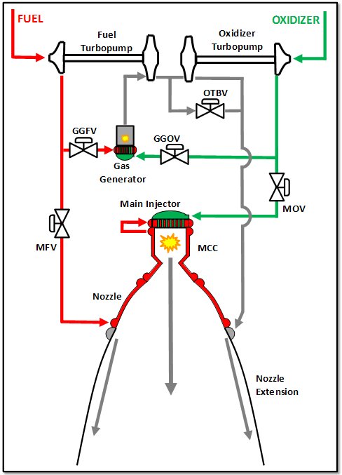
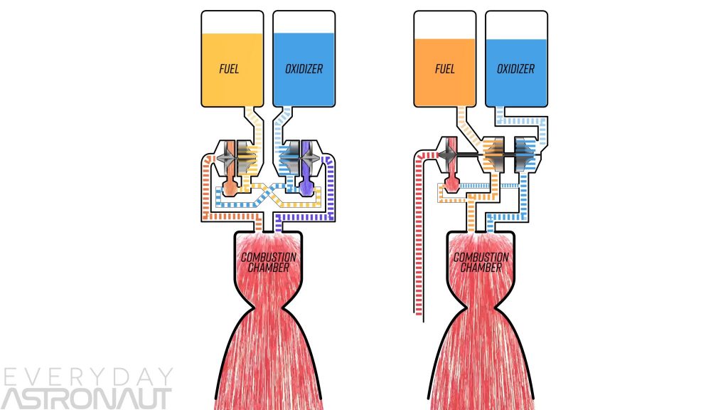
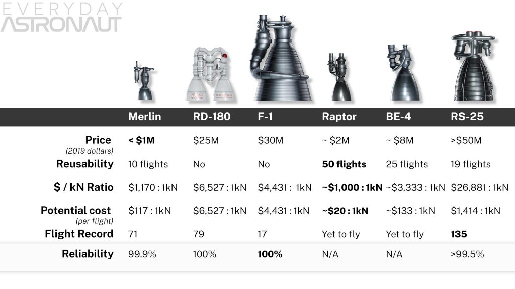
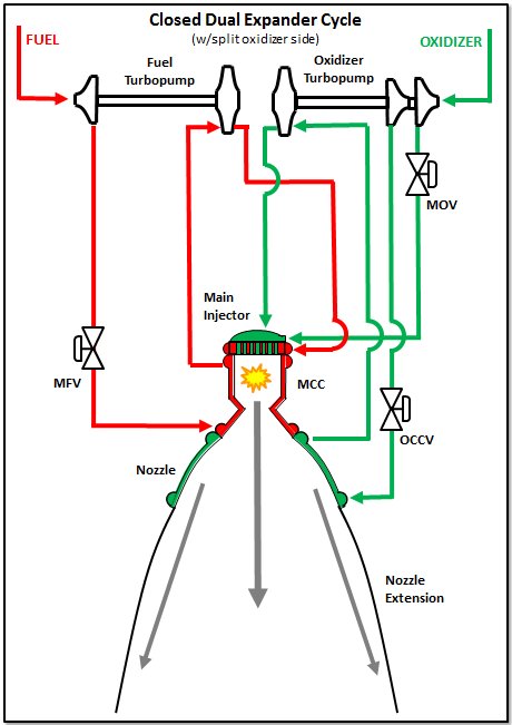
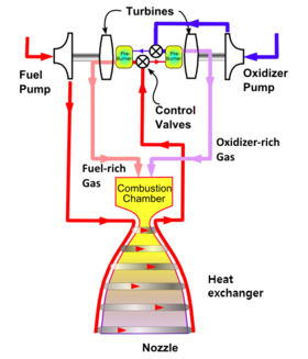
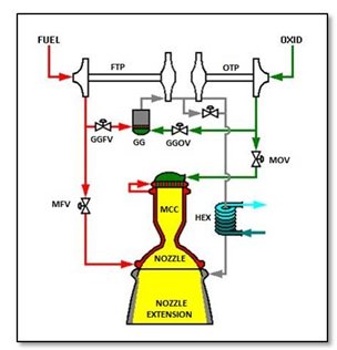
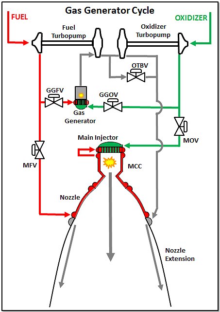
Merlin engines use rp 1 and liquid oxygen as rocket propellants in a gas generator power cycle.
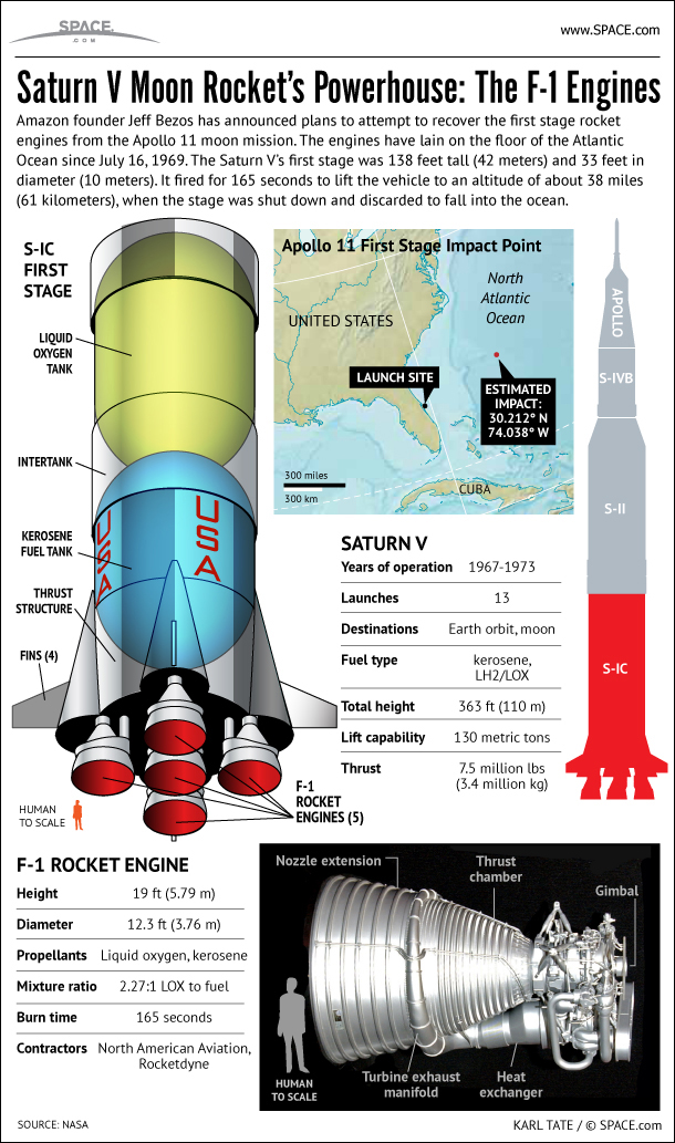
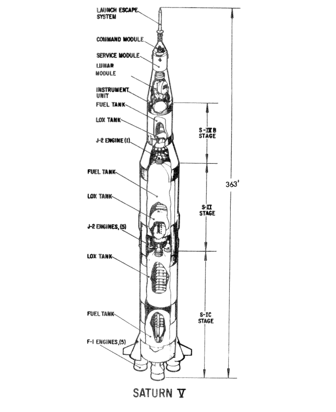
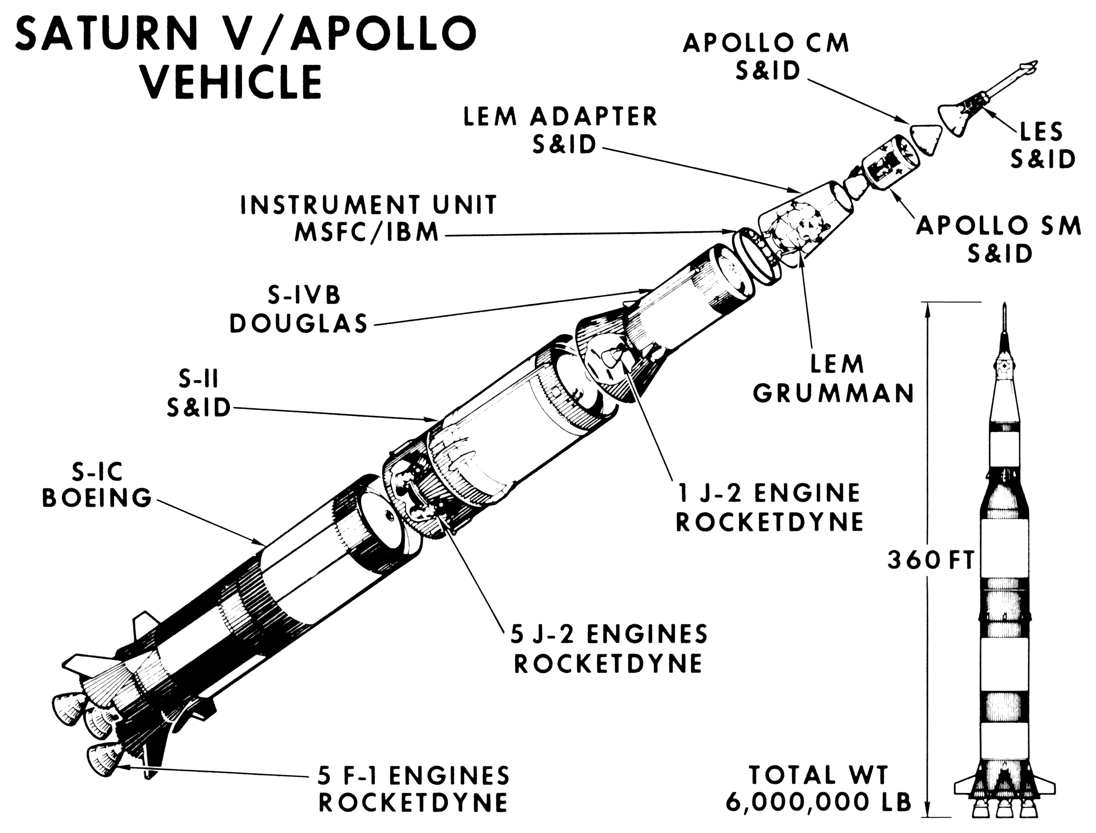
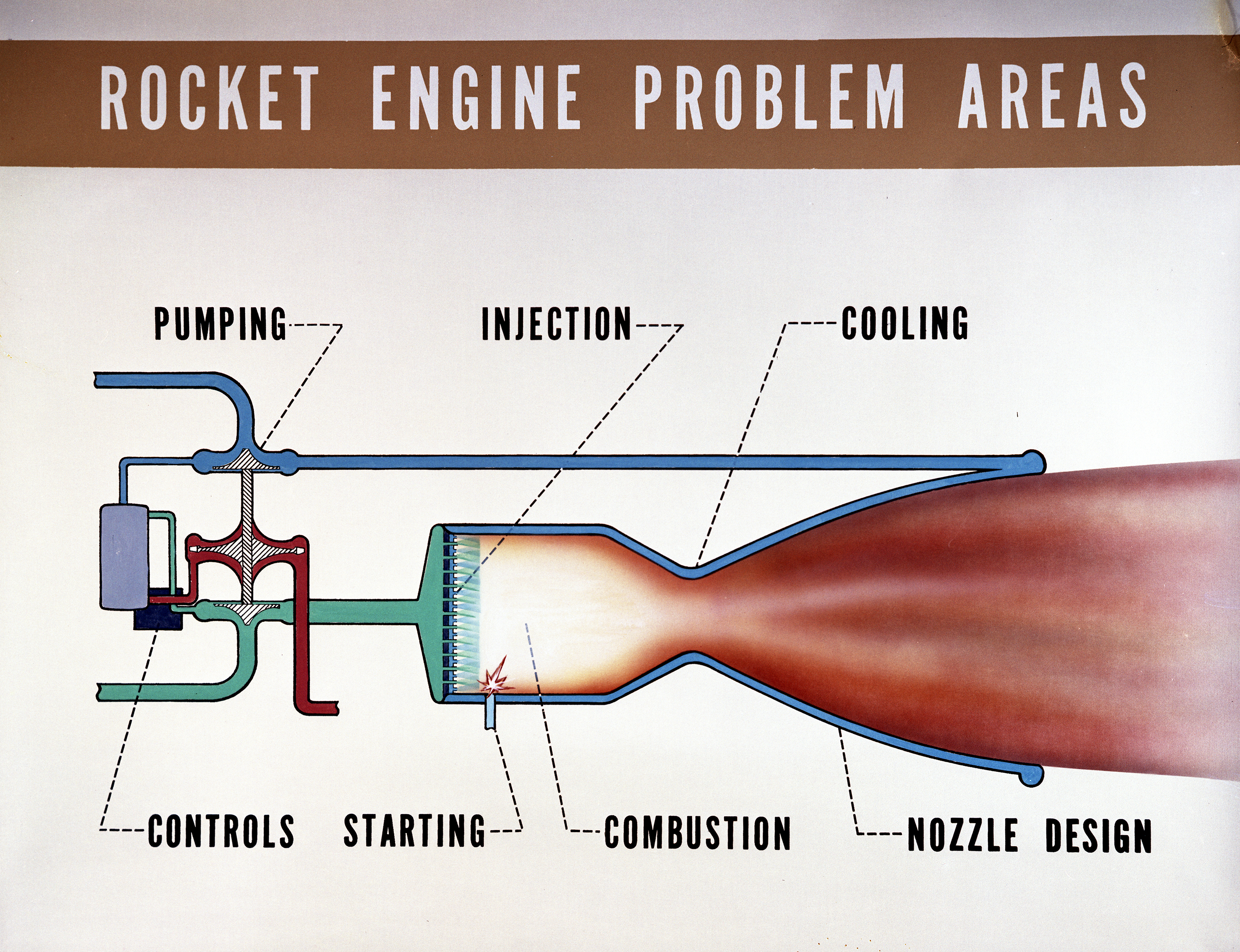
Schematic f1 rocket engine diagram. Five f 1 engines were clustered at the bottom of the saturn v rocket used to launch the apollo lunar missions into space. The spacex merlin is a family of rocket engines developed by spacex for use on its falcon 1 falcon 9 and falcon heavy launch vehicles. Many good image inspirations on our internet are the most effective image selection for f1 rocket engine diagram. Lets try to make this site a valuable resource for ho train collectors and modelers.
The merlin engine was originally designed for sea recovery and reuse. Estes rocket engine diagram this is a relatively typical end burning model rocket engine construction where a clay nozzle is rammed in the end of the tube and a solid black powder rocket fuel grain is then rammed above the nozzle. Vulcain rocketdyne h 1 wikiwand reference spacecraft engines rl10 amazon goddard rocket engine design graphic t shirt clothing reference spacecraft engines reference spacecraft engines reference spacecraft engines reference spacecraft engines reference spacecraft engines this kind of image f1 rocket engine diagram f 1 rocket engine earlier mentioned can be classed havingplaced through. At liftoff the stages five f 1 rocket engines ignite and produce 75 million pounds of thrust.
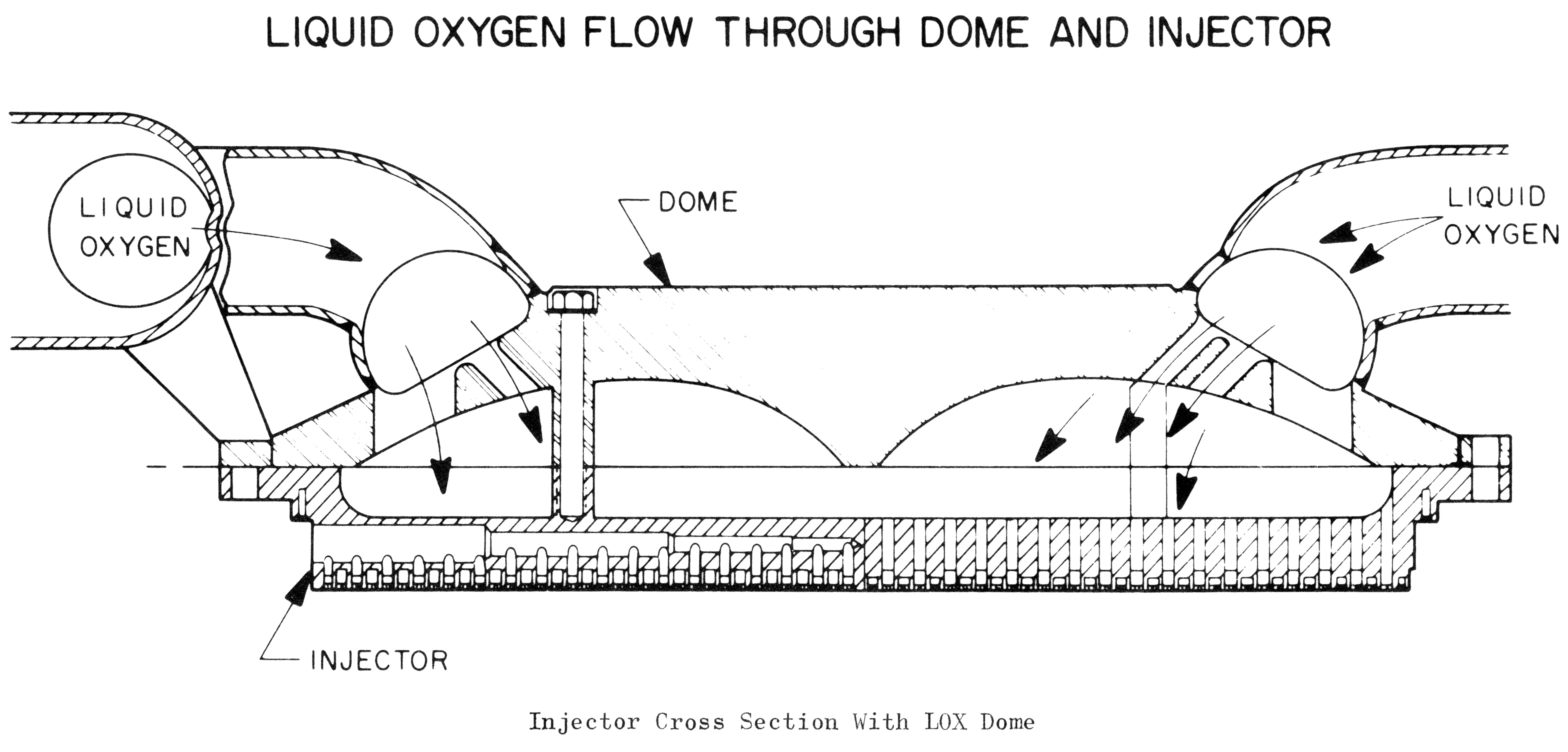
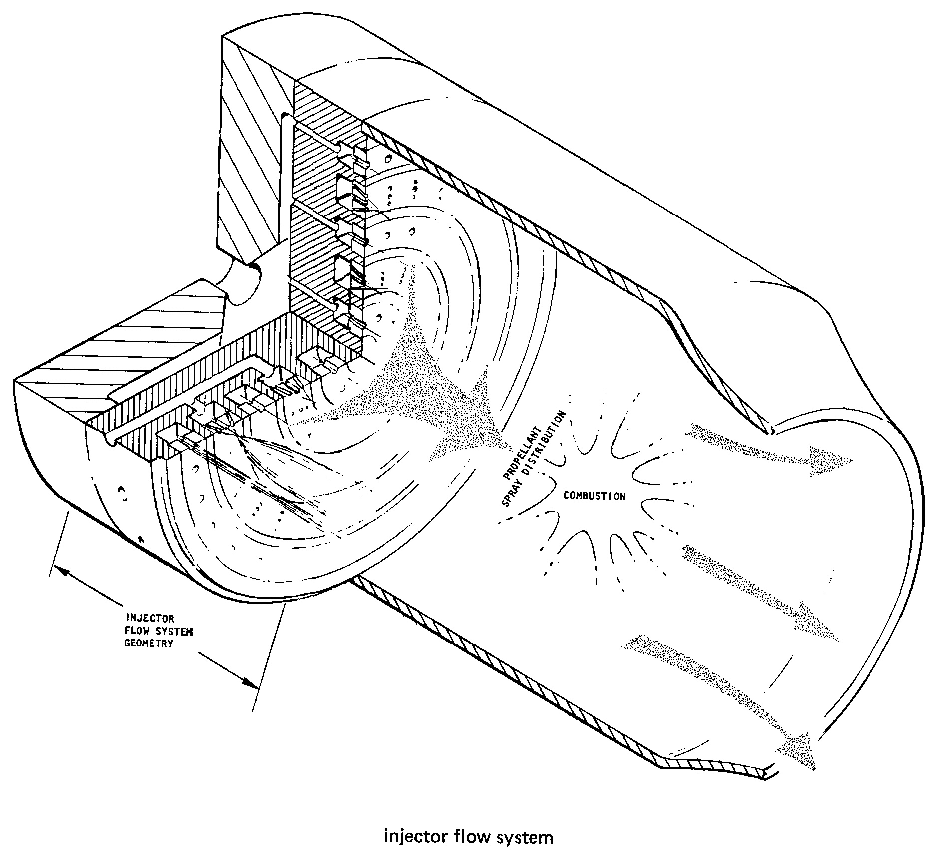
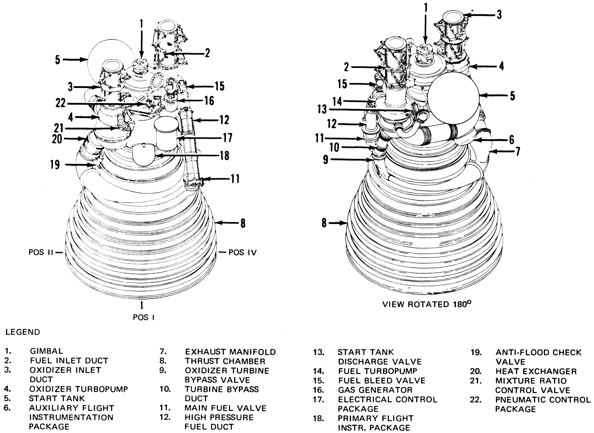
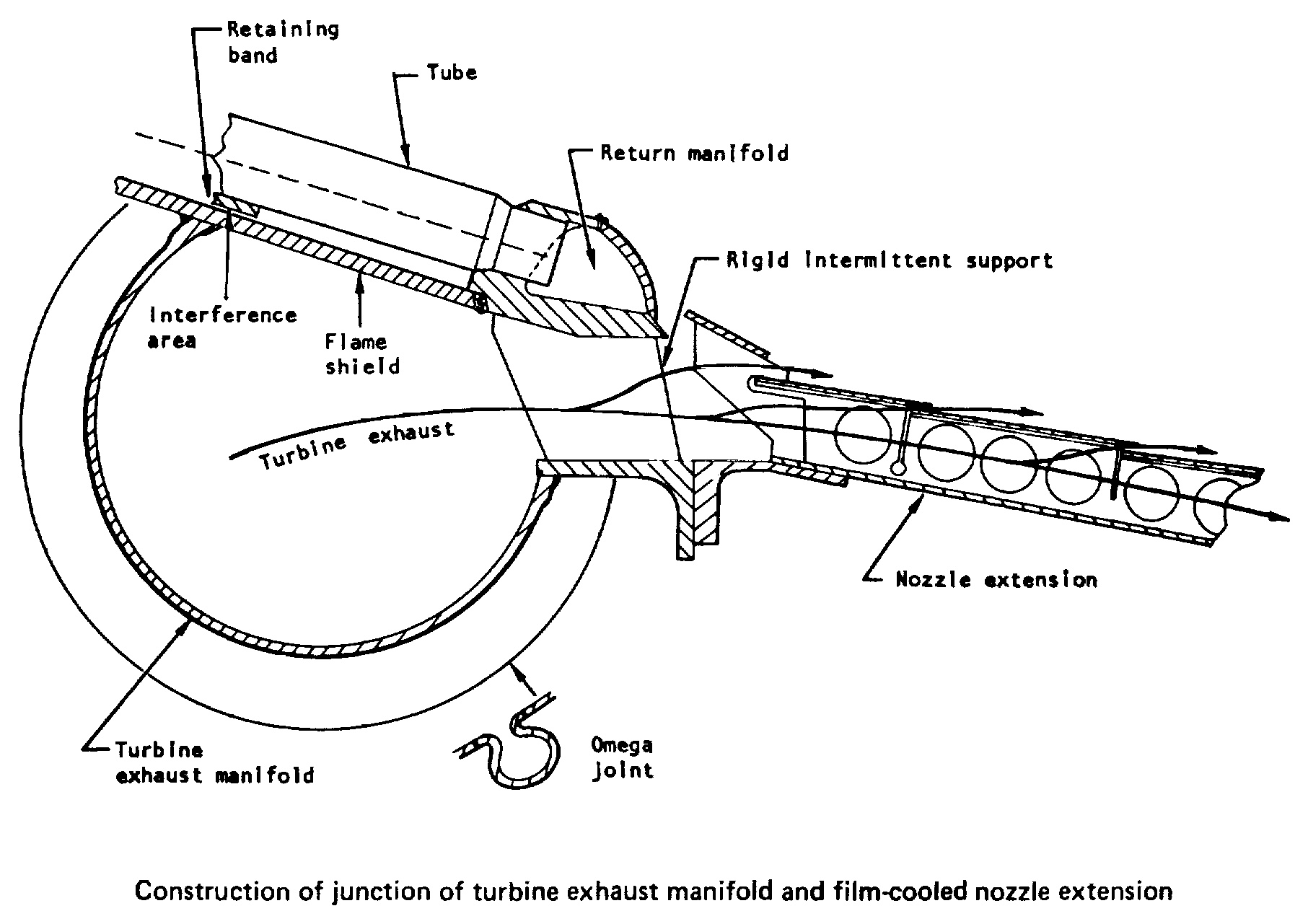
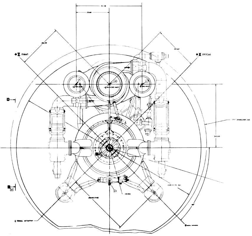
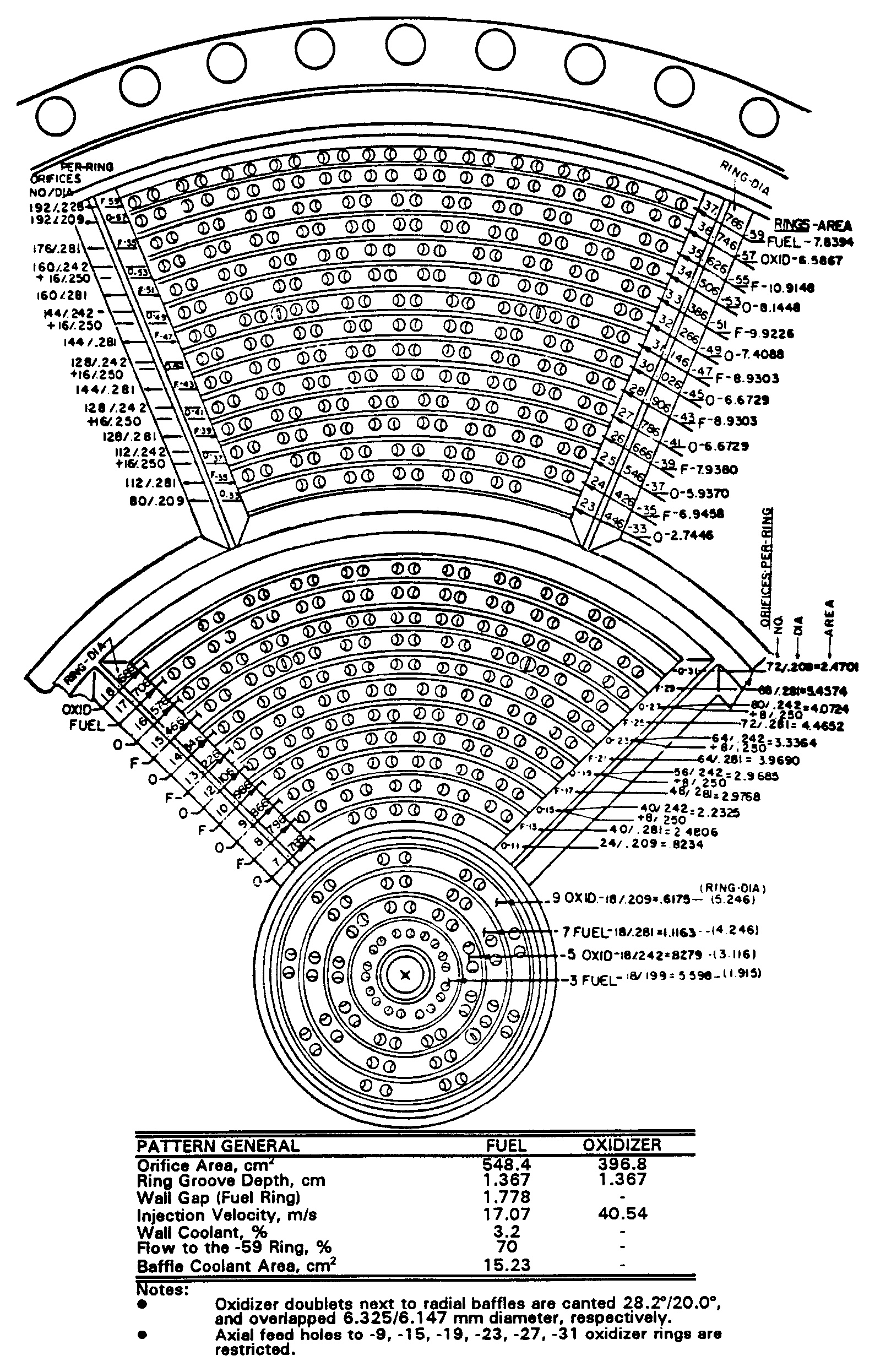
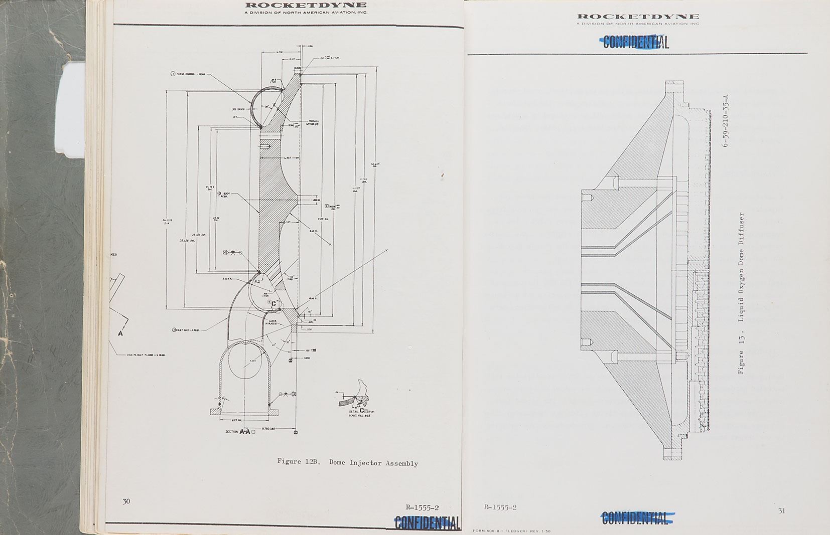
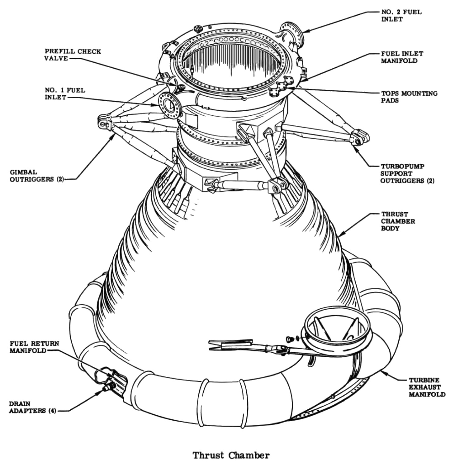
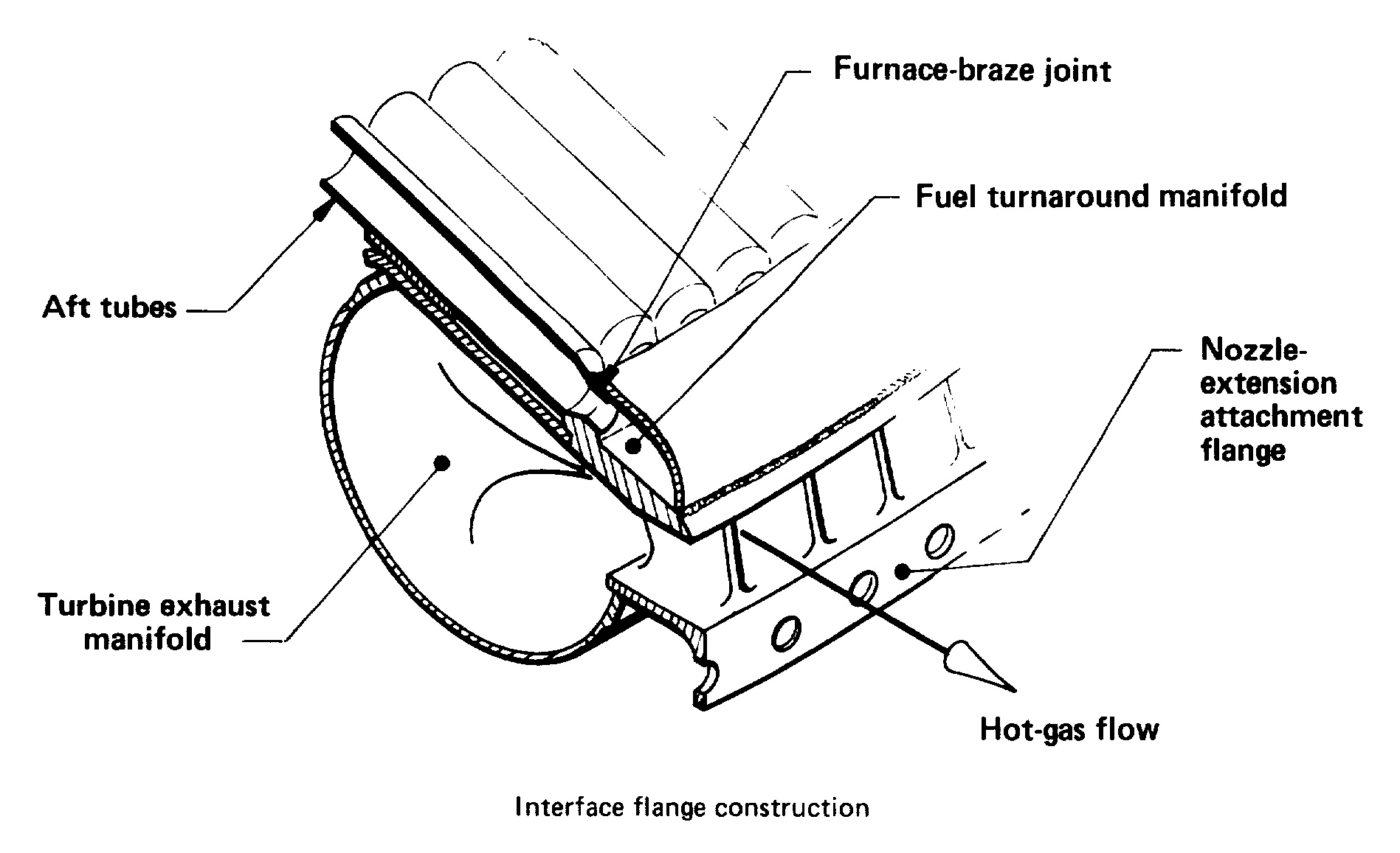
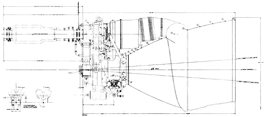
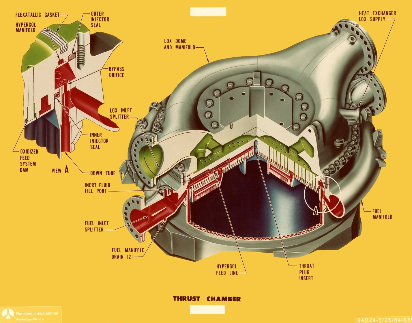
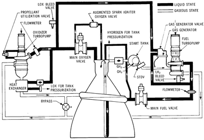
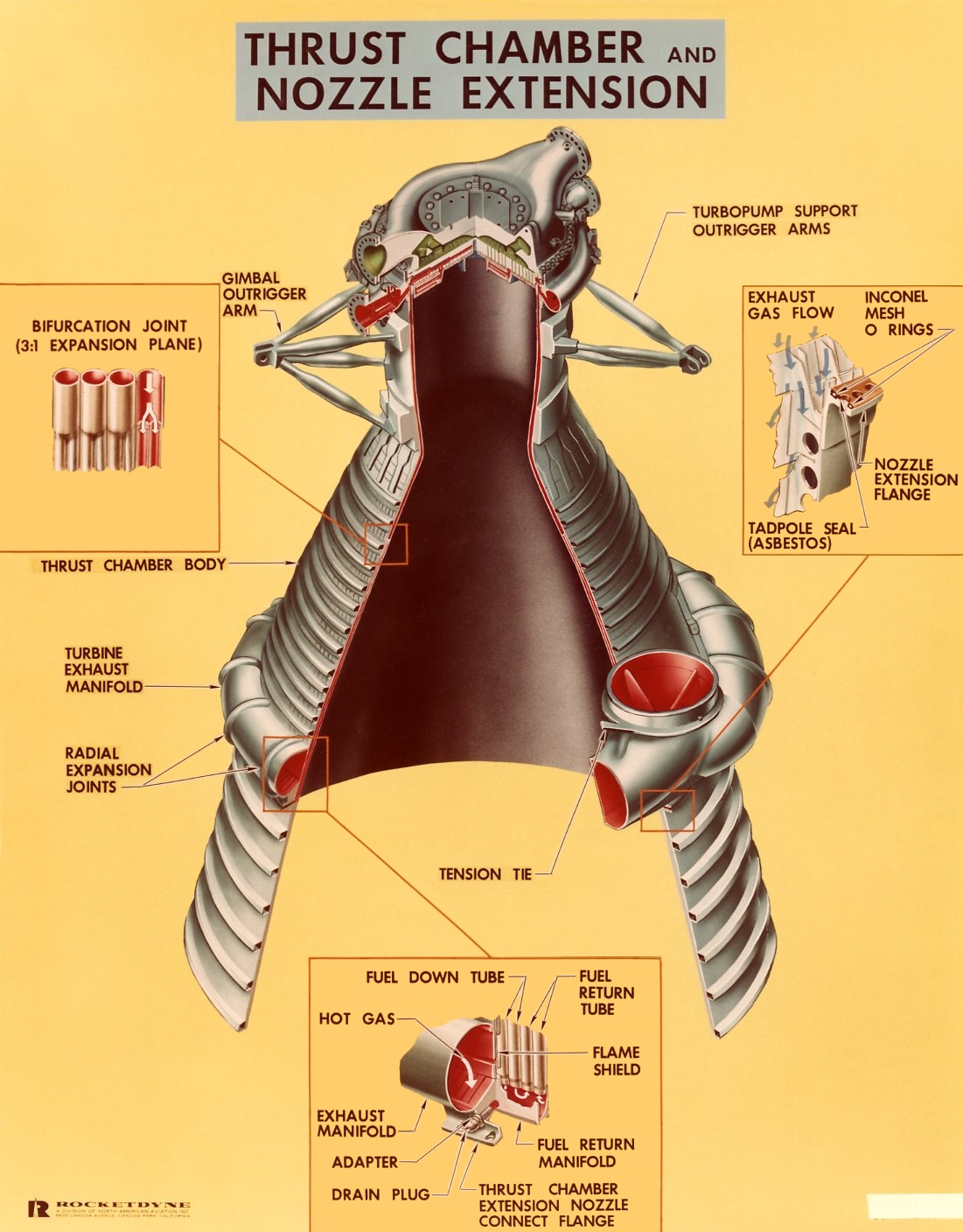
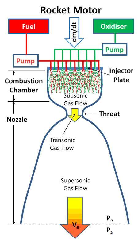
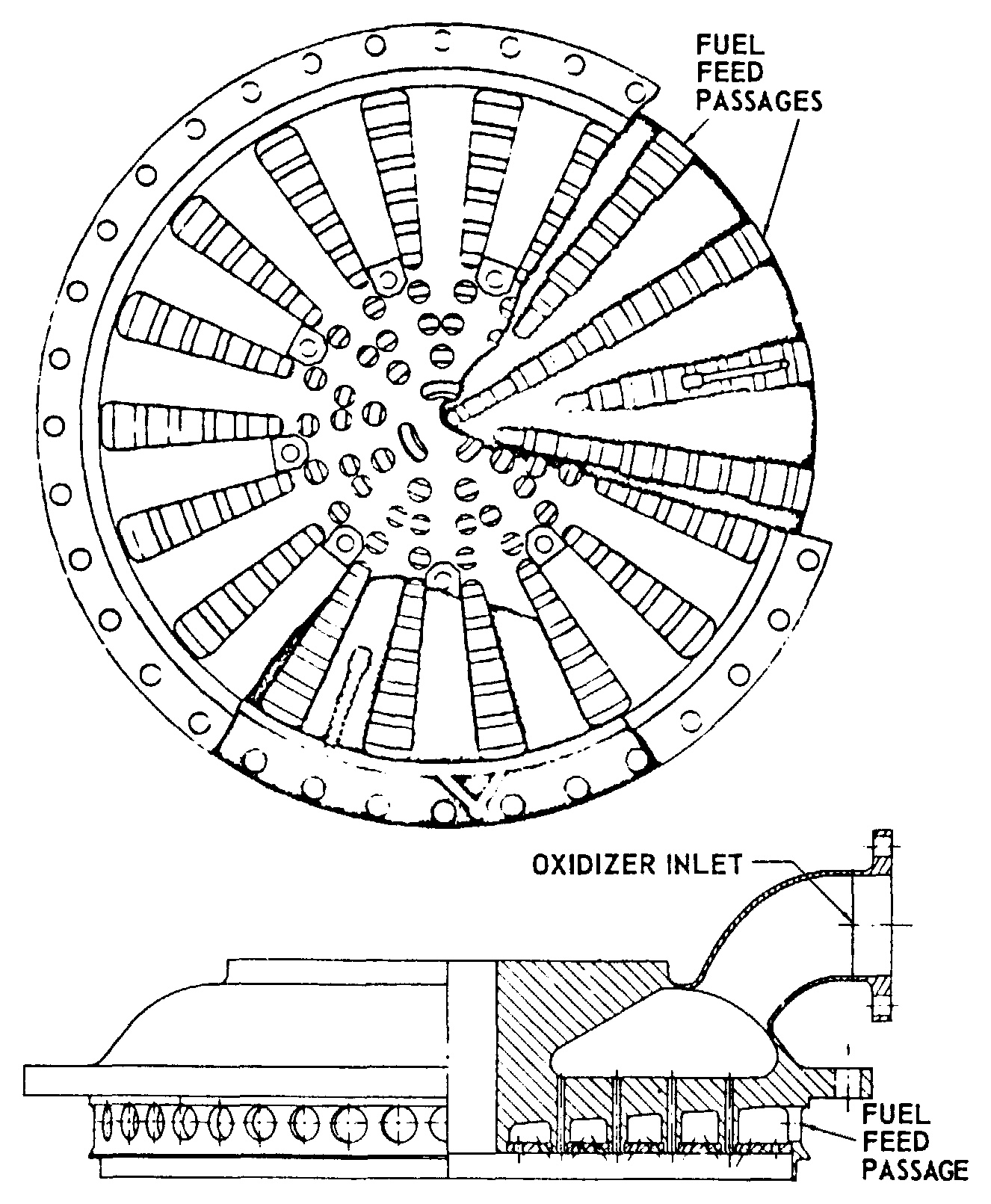
Diagram of the f 1 engine. Image of rocket engine liquid fuel f 1 rocket engine liquid fuel f 1 rocket engine liquid fuel f 1 we collect a lot of pictures about f1 rocket engine diagram and finally we upload it on our website. The injector at the heart of merlin is of the pintle type that was first used in the apollo. Explosive bolts fire and.
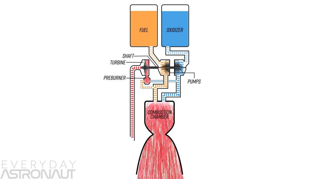
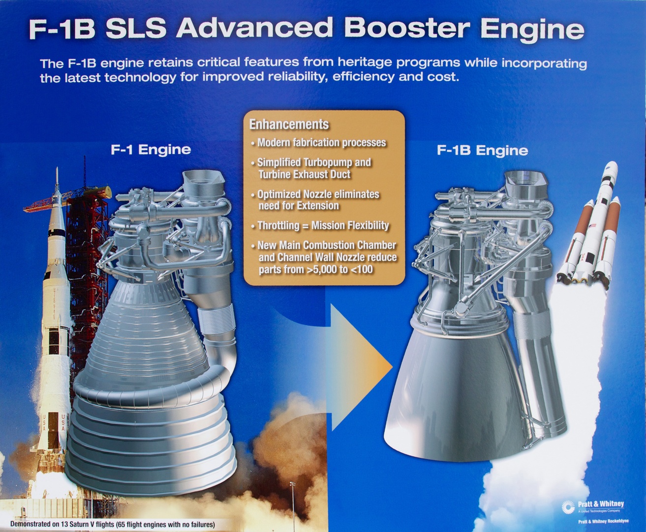
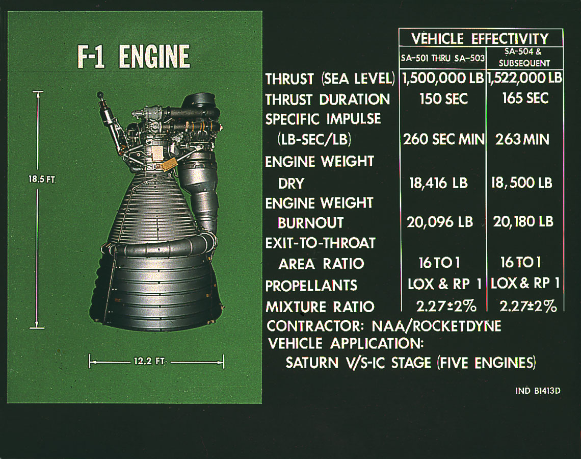
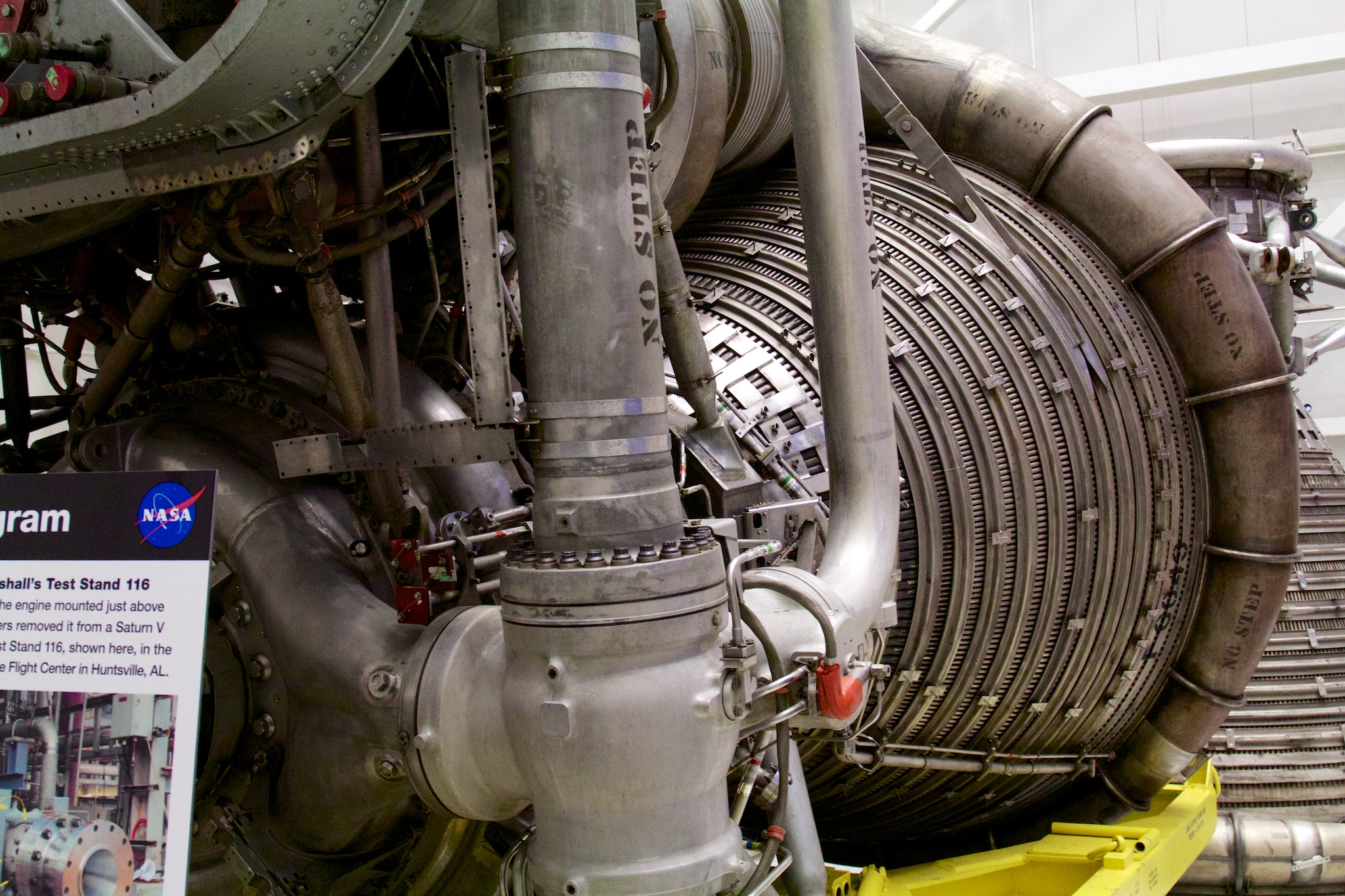
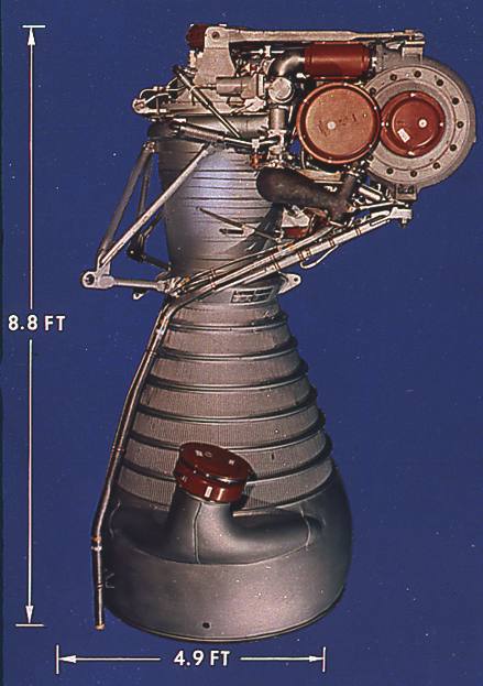
If you are in possession of any ho train enginecar assembly diagrams brochure or catalog that are not listed within this site please contact me about posting them here in this section. There is no hollow core going up into the black powder grain therefore the name end burner. The f 1 is a gas generator cycle rocket engine developed in the united states by rocketdyne in the late 1950s and used in the saturn v rocket in the 1960s and early 1970s. The f 1 rocket engines are on display at the national air and space museum in the apollo to the moon exhibit.
The liquid fueled engine was used during the apollo program and sat at the bottom of the saturn v. Five f 1 engines were used in the s ic first stage of each saturn v which served as the main launch vehicle of the apollo programthe f 1 remains the most powerful single combustion chamber liquid propellant rocket engine.
